iSCSI Storage for Your SQL Server Systems
iSCSI storage systems are fast becoming a viable, alternative I\O medium. Speeds of up to 10Gboe are readily attainable. The last few years have seen the range of storage systems grow from open source systems such as FreeNAS and OpenFiler to paid systems like StarWinds and even Microsoft Windows 2008 storage server. Then, of course, you have the main stream products like NetApp Filers which offer either FC or iSCSI storage.
The Windows operating system now offers a stable iSCSI driver and Microsoft also offer the MPIO driver too, ideal for I\O multi-pathing. The 2 components require careful configuration and it’s important to note that the iSCSI driver does not support teamed NICs for the iSCSI connection, something which seems to be either accidentally missed or just plain ignored. Rather, the redundancy\performance capabilities for your iSCSI attached storage should be left to the use of iSCSI driver policies which we will see later, as the NIC teaming software moves the control of the NICs outside of the iSCSI driver.
What is iSCSI?
iSCSI is the acronym for Internet Small Computer Systems Interface. It is a method of transmitting and receiving SCSI commands over TCP\IP networks. In traditional SCSI systems you have mediums for transferring data across computer systems and their peripherals. SCSI commands are sent from a SCSI interface to a SCSI disk for instance, requesting to write or read a block of data. Your SCSI disks inside your server are simply receiving sets of commands from the SCSI interface (typically a SCSI controller).
iSCSI provides the transport of these commands across IP internet protocols, instead of the traditional fast, wide or ultra wide SCSI interfaces. iSCSI can use standard Ethernet cards on your host system although better performance will be realised by using dedicated offload engine cards or Host Bus Adapters. The biggest advantage of iSCSI is that it does not require complex\expensive Fibre Channel equipment that you see in large Storage Area Networks. With iSCSI, you are able to leverage "off the shelf" Ethernet technologies and equipment, this generally requires no further training, as the components in use form standard Ethernet networks.
The iSCSI topolgy typically has the following endpoints
- Initiator (or client)
- Target (or storage server)
Initiators may be software based (Microsoft iSCSI Initiator) or hardware based (iSCSI host bus adapter) from the client endpoint, in our scenario we are using the software based initiator on our Windows Server client.
Targets usually take the form of data LUNs presented via Target Portals. The portals themselves, usually default to the TCP port 3260, this is widely accepted as the default for this protocol. Each storage target represents a SCSI target device, these are uniquely identified using Logical Unit Numbering.
Both the initiators and the targets use a unique naming convention known as an Iscsi Qualified Name (IQN). These are unique to each entity and appear as follows;
Initiator example:
iqn.1991-05.com.microsoft:iscsi-client
Target example:
iqn.2007-09.jp.ne.peach.istgt:disk0
The defaults above are from the configurations generated by the standard installs of the products used in this article. The Internet Engineering Task Force define IQNs as follows:
This iSCSI name type can be used by any organization that owns a domain name. This naming format is useful when an end user or service provider wishes to assign iSCSI names for targets and/or initiators. To generate names of this type, the person or organization generating the name must own a registered domain name. This domain name does not have to be active, and does not have to resolve to an address; it just needs to be reserved to prevent others from generating iSCSI names using the same domain name. Since a domain name can expire, be acquired by another entity, or may be used to generate iSCSI names by both owners, the domain name must be additionally qualified by a date during which the naming authority owned the domain name. For this reason, a date code is provided as part of the "iqn." format.
The iSCSI qualified name string consists of:
- The string "iqn.", used to distinguish these names from "eui." formatted names.
- A date code, in yyyy-mm format. This date MUST be a date during which the naming authority owned the domain name used in this format, and SHOULD be the first month in which the domain name was owned by this naming authority at 00:01 GMT of the first day of the month. This date code uses the Gregorian calendar. All four digits in the year must be present. Both digits of the month must be present, with January == "01" and December == "12". The dash must be included.
- A dot "."
- The reversed domain name of the naming authority (person or organization) creating this iSCSI name.
- An optional, colon (:) prefixed, string within the character set and length boundaries that the owner of the domain name deems appropriate. This may contain product types, serial numbers, host identifiers, or software keys (e.g., it may include colons to separate organization boundaries). With the exception of the colon prefix, the owner of the domain name can assign everything after the reversed domain name as desired. It is the responsibility of the entity that is the naming authority to ensure that the iSCSI names it assigns are worldwide unique. For example, "Example Storage Arrays, Inc.", might own the domain name "example.com".
The following are examples of iSCSI qualified names that might be generated by "EXAMPLE Storage Arrays, Inc."
Naming String defined by
Type Date Auth "example.com" naming authority
+--++-----+ +---------------+ +--------------------------------------------+
| || | | | | |
iqn.2001-04.com.example:storage:diskarrays-sn-a8675309
iqn.2001-04.com.example
iqn.2001-04.com.example:storage.tape1.sys1.xyz
iqn.2001-04.com.example:storage.disk2.sys1.xyz
For the full RFC details please see this link http://www.ietf.org/rfc/rfc3720.txt
How does it work?
There are various iSCSI Initiators available, for different host operating systems. Here we are covering the Microsoft iSCSI Initiator for the Windows Server platform. The iSCSI driver uses sessions to connect to the remote storage. There may be multiple sessions (using MPIO) or single sessions with multiple connections (MCS). They each have their pros and cons and it’s commonly broadcast that in most cases single session has the edge, although this has still to be conclusively proven. MPIO has a wider compatibility and operates at a higher level across initiator technologies, whereas MCS is specific to the Microsoft iSCSI initiator.
These sessions can, and most definitely should, use either CHAP authentication or IPSec or both, for increased security across the iSCSI network. It should also be noted that segregating the iSCSI traffic will also help to secure the data travelling "across the wire", to this end the iSCSI network should ideally be routed for multiple physical paths (i.e. separate switches for separate paths) to avoid impacting security, performance and having a network hardware failure affecting the efficiency\operation of the whole iSCSI network. You can, if you have the appropriate switch gear, use VLANs across chosen switch ports but as already stated for true redundancy, security and good performance you will want to use segregated hardware. After all, there’s no point providing multiple paths if they all use the same physical switches!
Multiple NICs on the server may be configured into separate networks and these may then be incorporated into multiple sessions\connections through the iSCSI driver. The sessions themselves use a series of policies for failover and redundancy, these are detailed below
MCS
- Fail Over Only - This policy utilises one path as the active path and designates all other paths as standby. Upon failure of the active path the standby paths are enumerated in a round robin fashion until a suitable path is found.
- Round Robin - This policy will attempt to balance incoming requests evenly against all paths.
- Round Robin With Subset - This policy applies the round robin technique to the designated active paths. Upon failure standby paths are enumerated round robin style until a suitable path is found.
- Least Queue Depth - This policy determines the load on each path and attempts to re direct I\O to paths that are lighter in load.
- Weighted Paths - This policy allows the user to specify the path order by using weights. The larger the number assigned to the path the lower the priority.
MPIO
As above plus
- Least Blocks - This policy sends requests to the path with the least number of pending I\O blocks.
Before implementing the Microsoft iSCSI Initiator you must confirm with your storage vendor, the compatibility of your storage mediums for MPIO or MCS, depending on which method you intend to use. The design should mitigate any path failure so a valid path may still be found through to the storage in the event of a failure.
MPIO can use Device Specific Modules, these are custom drivers developed by your storage vendor to work with MPIO specifically for their storage hardware. The DSM controls the storage requests across the multiple paths and also takes care of any failure scenarios, ensure you research fully any required drivers that may be requied for your storage system. Utilising iSCSI you have instant support for fail over cluster shared storage, including the SCSI-3 persistent reservations required by Windows 2008. iSCSI storage is presented to the initiator as block level storage, this enables the provisioning of shared storage to your fail over cluster nodes. For Windows 2003 cluster nodes there are some changes that need to be applied, these are detailed in Appendix A at the end of this article.
So, when using the Microsoft iSCSI initiator for storage provisioning, how exactly do you configure multi-pathing to provide either failover and\or load balancing?
As always, this is very easy to demonstrate using a pair of virtual machines, one for the FreeNAS server (the iSCSI target) and one for the Windows 2008 server (the iSCSI initiator).
I am using FreeNAS v0.7.5 and Windows 2008 R2 Enterprise. I have 3 vNICs per machine and 3 virtual switches. The first NIC on each machine constitutes a public connection and is connected to the first switch (Public). The second NIC is connected to the second virtual switch (iSCSI_1) and emulates a segregated SAN network. The third NIC is connected to the third virtual switch (iSCSI_2) and emulates a second segregated SAN network. At the VMWare server level I have 3 virtual switches, my IP ranges in use are as follows
172.168.10.0 255.255.255.0 VMNet1 Public
192.168.92.0 255.255.255.0 VMNet2 iSCSI_1
192.168.93.0 255.255.255.0 VMnet3 iSCSI_2
A quick glance at the Freenas configuration shows the following
- LAN management NIC using 172.168.10.5
- OPT1 network interface using 192.168.93.5
- OPT2 network interface using 192.168.92.5
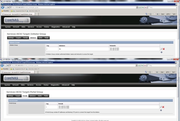
On the virtual NAS machine I have 1 virtual disk sliced into 3 LUNs. The iSCSI target settings have the following configuration:
Firstly, let's configure for multiple connections per session (MCS).
If you are configuring for MCS you do not need to, in fact you should not, install the MPIO driver\feature to the Windows server. We will be assuming that you have already created your LUNs on the filer\FreeNAS\etc.
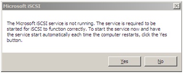
The first time you open the iSCSI Initiator you may see the message below, click "Yes" to ensure that the iSCSI service starts automatically each time the Windows Server operating system boots.
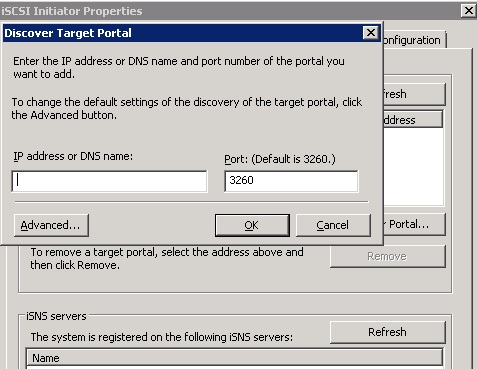
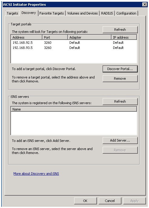
On the iSCSI Initiator Properties dialog switch to the "Discovery" tab. Click the "Discover Portal" button and enter your storage target IP addresses (interfaces OPT1 and OPT2 on the NAS).
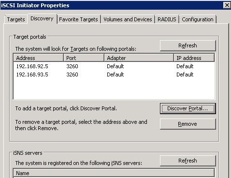
Once both portals have been discovered you should see the following.
(If you have firewalls operating don't forget to set ACLs for port access over port 3260)
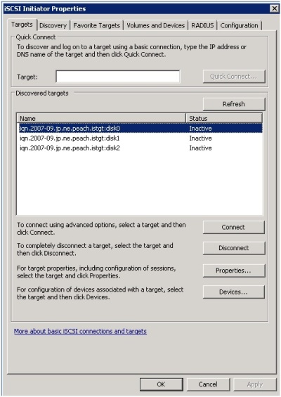
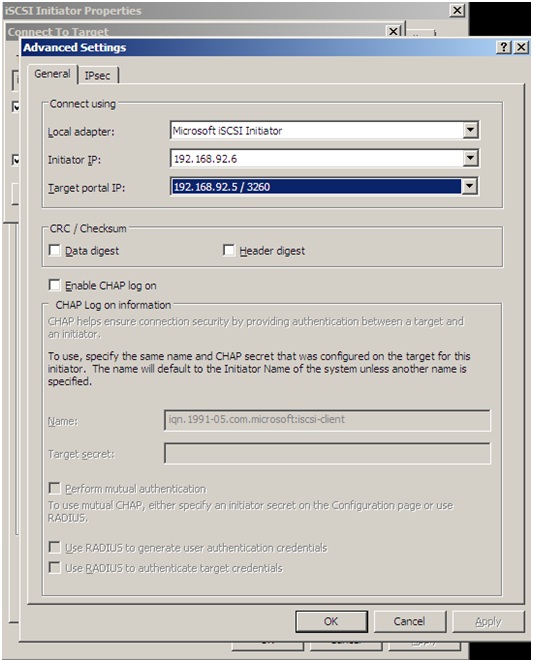
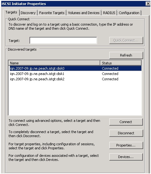
Switch to the "Targets" tab and you will see the 3 exposed LUNs. Select the first LUN and click "Connect", click the "Advanced" button and select the 1st initiator IP and portal IP. Click "OK" to both dialogs to return to the targets dialog. Do this for all 3 targets.
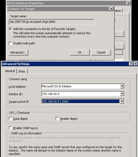
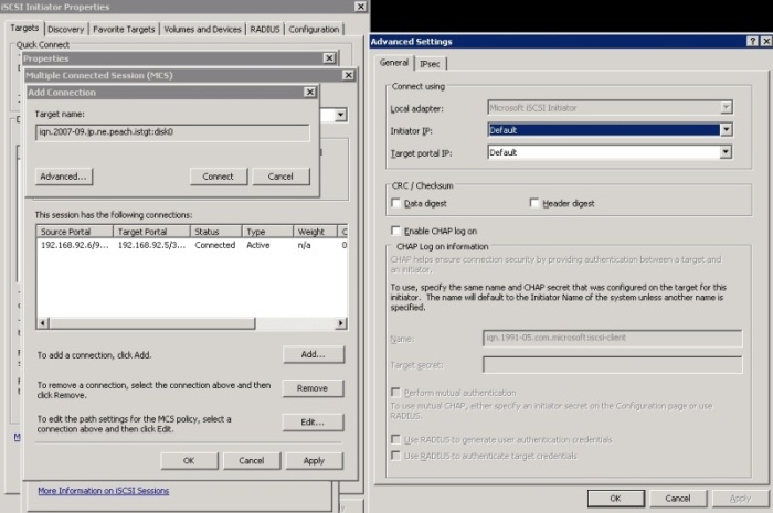
Back at the "Targets" tab select the first target and click the "Properties" button. On the properties window, select the checkbox for the existing single session and then click the "MCS" button. On the MCS dialog window click "Add" to add a new connection. Click the "Advanced" button and select the 2nd initiator and portal IP's. Click "OK" and then "Connect". To finish, click "OK" to the MCS dialog to return to the target properties.
Select your MCS policy as shown below and click "OK", you are back to the target properties window.
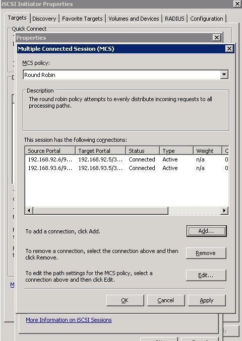
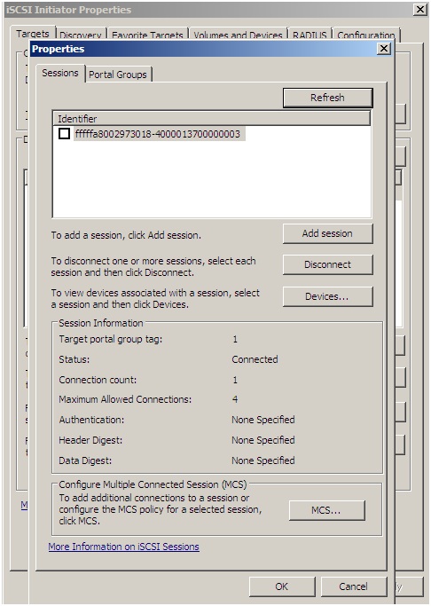
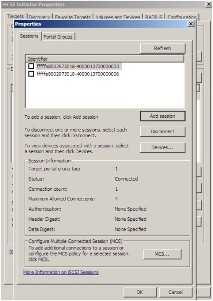
On the properties window, you will now have 2 active connections within your single session as shown below.
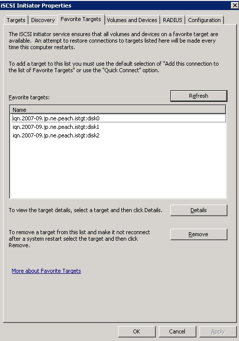
Select each of the remaining connections and complete the steps detailed above. Once you have completed the steps above switch to the Favourite Targets tab and you will see the entries for your 3 targets.
Switch to the "Volumes and Devices" tab and bind all available disks. The easiest way to do this is to click the "Auto Configure" button.
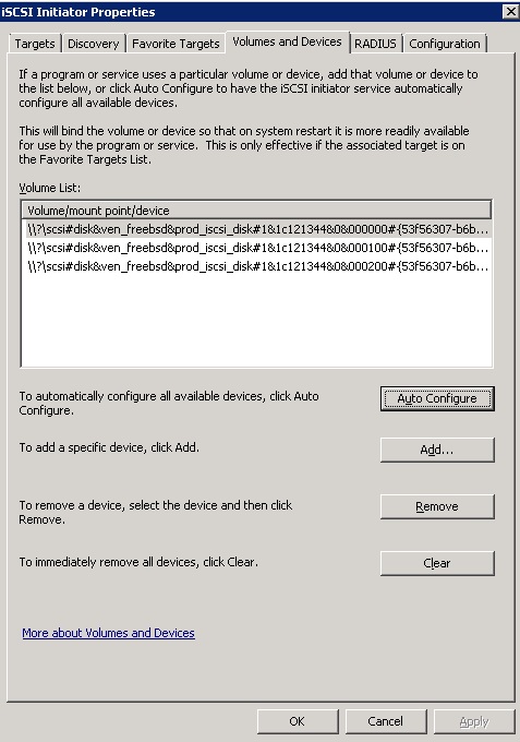
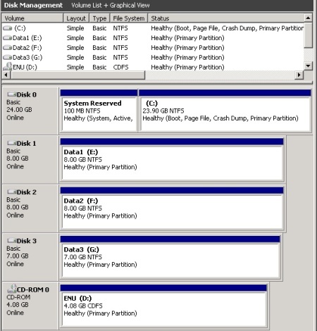
You may now close the iSCSI properties window. With the disks initialised and formatted we see the following.
Now let's look at how to configure an iSCSI target for MPIO using the iSCSI initiator. We will be assuming that you have already created your LUNs on the filer\FreeNAS\etc and that the iSCSI service is configured to auto start (as shown previously).
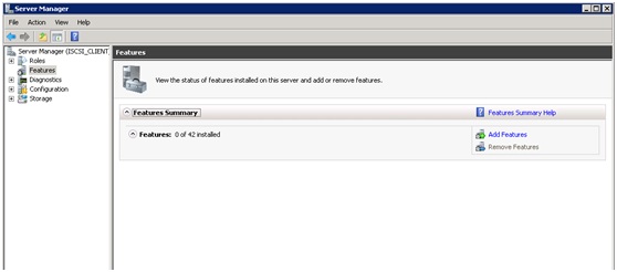
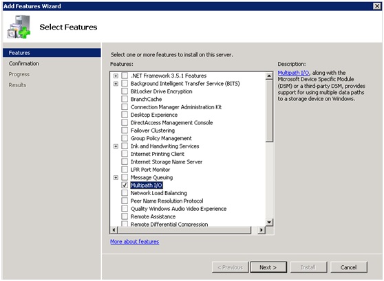
First we need to enable the MPIO feature as shown in the screenshots below
The first step is to set portal discovery as shown below. Click the "Discover Portal" button and enter the Portal Discovery details for both portals, you should see the following.
(If you have firewalls operating don't forget to set ACLs for the connections over port 3260).
Switching to the "Targets" tab you should now see the exposed targets. Select the first target and click the "Connect" button.
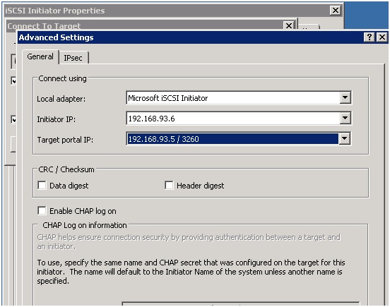
On the connection tab, ensure you check both checkboxes for the multi-path and favourite targets options. Click the "Advanced" button to set the initiator and portal IP's.
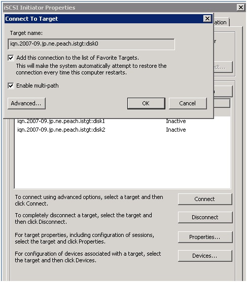
On the advanced settings tab set the initiator IP and the portal IP. Configure any security as required and click "OK". Finally click "OK" again to complete the session connection.
Complete the same steps for the remaining targets and that’s the first logon sessions created for these targets.
To create further logon sessions for your chosen target(s), highlight them and click the “Properties” button. On the "Sessions" tab click the "Add Session" button.
Click the “Advanced” button as before and select the adapter type, IP Address and target portal. Click “OK” to confirm and then click "OK" again to complete the connection.
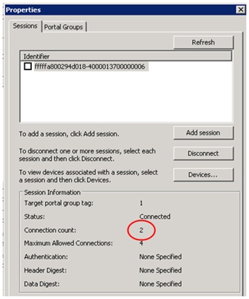
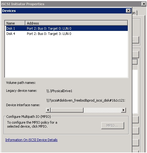
Shown below is the session information, showing the 2nd session we have just created for this target. Complete the same steps for the remaining targets. Clicking the "Devices" button shows the next screenshot
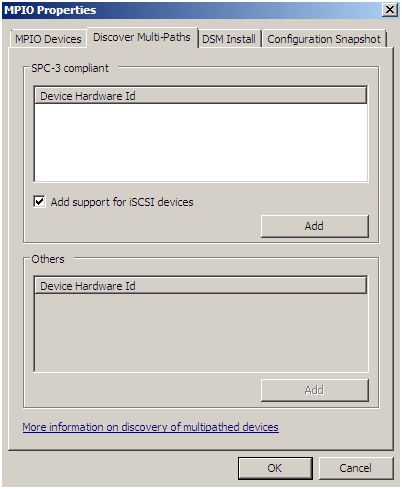
MPIO is not currently available, we need to go enable this now. Close the iSCSI Initiator properties and open the MPIO console.
Go to the Discover Multi-Paths tab and select the checkbox for "Add support for iSCSI devices". Click the "Add" button.
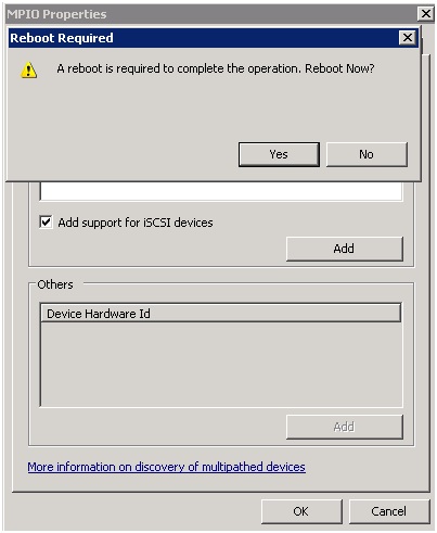
When enabling the MPIO support a reboot will be required, complete this before proceeding any further.
Open the iSCSI Initiator properties and select your first target, click the “Devices” tab and select the “MPIO” button to open the dialogs shown below. On the “MPIO” dialog you will see the load balance policy details and device sessions. Select your policy and click “OK” to confirm and close the “Device Details” dialog. Click “OK” again, to close the “Devices” tab. Complete this for all remaining targets.
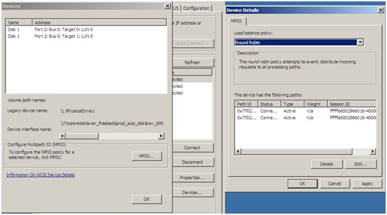
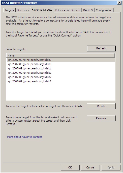
On the iSCSI Initiator Properties dialog select the “Favourite Targets” tab. At this point don’t be alarmed, for multiple sessions you will see multiple targets here (one target for each session).
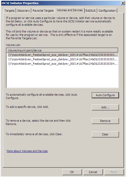
Finally bind all devices on the "Volumes and Devices" tab, the easiest way to achieve this is to click “Auto Configure”. Click "OK" to close the iSCSI Initiator properties dialog.
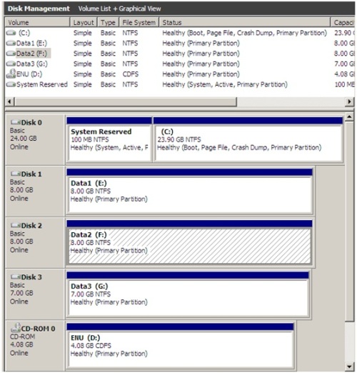
Go into Windows disk management and initialise the new disks, create partitions and format the file systems. Once this is done, a small test as shown below will demonstrate our Round Robin load balanced storage using mutli-pathing.
Copying a DVD image from the CD drive to drive F: shows the following stats for the 2 iSCSI NICs.
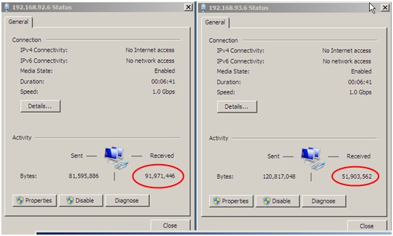
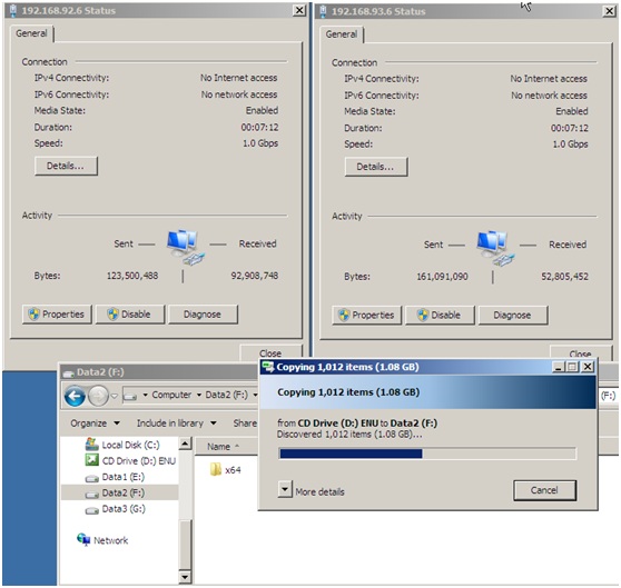
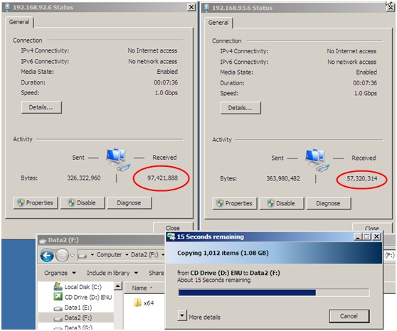
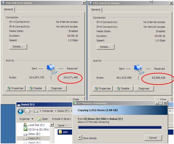
As you can see from the NIC stats the data is distributed evenly amongst the 2 NICs, not all of the MPIO\MCS policies provide round robin, some provide failover or a combination of failover and round robin. As a further test, during a large file copy go to the virtual machine properties in the VMWare Server console and disconnect one of the iSCSI vNICS, the process should carry on unhindered. Using the Round Robin policy I was able to observe a noticeable reduction in the file copy performance during the disconnection. Disconnecting both vNICs on the Windows 2008 server results in a loss of the iSCSI disks, much as you would expect.
SQLIO Results
Looking at the SQLIO results we can see the following;
| Queue depth 32 | Queue depth 64 | Queue Depth 128 |
|---|
|
8KB Random writes
throughput metrics:
IOs/sec: 43.81
MBs/sec: 0.34
latency metrics:
Min_Latency(ms): 19
Avg_Latency(ms): 1454
Max_Latency(ms): 5191
|
8KB Random writes
throughput metrics:
IOs/sec: 43.71
MBs/sec: 0.34
latency metrics:
Min_Latency(ms): 8
Avg_Latency(ms): 2910
Max_Latency(ms): 6168
|
8KB Random writes
throughput metrics:
IOs/sec: 40.69
MBs/sec: 0.31
latency metrics:
Min_Latency(ms): 12
Avg_Latency(ms): 6094
Max_Latency(ms): 9915
|
|
8KB Random reads
throughput metrics:
IOs/sec: 67.45
MBs/sec: 0.52
latency metrics:
Min_Latency(ms): 18
Avg_Latency(ms): 944
Max_Latency(ms): 1709
|
8KB Random reads
throughput metrics:
IOs/sec: 66.95
MBs/sec: 0.52
latency metrics:
Min_Latency(ms): 20
Avg_Latency(ms): 1899
Max_Latency(ms): 3103
|
8KB Random reads
throughput metrics:
IOs/sec: 67.50
MBs/sec: 0.52
latency metrics:
Min_Latency(ms): 37
Avg_Latency(ms): 3744
Max_Latency(ms): 4157
|
|
64KB Random writes
throughput metrics:
IOs/sec: 38.37
MBs/sec: 2.39
latency metrics:
Min_Latency(ms): 39
Avg_Latency(ms): 1660
Max_Latency(ms): 5889
|
64KB Random writes
throughput metrics:
IOs/sec: 38.19
MBs/sec: 2.38
latency metrics:
Min_Latency(ms): 30
Avg_Latency(ms): 3320
Max_Latency(ms): 6969
|
64KB Random writes
throughput metrics:
IOs/sec: 39.06
MBs/sec: 2.44
latency metrics:
Min_Latency(ms): 20
Avg_Latency(ms): 6453
Max_Latency(ms): 8826
|
|
64KB Random reads
throughput metrics:
IOs/sec: 57.14
MBs/sec: 3.57
latency metrics:
Min_Latency(ms): 85
Avg_Latency(ms): 1115
Max_Latency(ms): 1533
|
64KB Random reads
throughput metrics:
IOs/sec: 57.58
MBs/sec: 3.59
latency metrics:
Min_Latency(ms): 141
Avg_Latency(ms): 2205
Max_Latency(ms): 2910
|
64KB Random reads
throughput metrics:
IOs/sec: 58.42
MBs/sec: 3.65
latency metrics:
Min_Latency(ms): 291
Avg_Latency(ms): 4318
Max_Latency(ms): 5162
|
|
8KB Sequential writes
throughput metrics:
IOs/sec: 762.36
MBs/sec: 5.95
latency metrics:
Min_Latency(ms): 0
Avg_Latency(ms): 83
Max_Latency(ms): 5813
|
8KB Sequential writes
throughput metrics:
IOs/sec: 894.73
MBs/sec: 6.99
latency metrics:
Min_Latency(ms): 0
Avg_Latency(ms): 142
Max_Latency(ms): 4544
|
8KB Sequential writes
throughput metrics:
IOs/sec: 915.90
MBs/sec: 7.15
latency metrics:
Min_Latency(ms): 0
Avg_Latency(ms): 278
Max_Latency(ms): 6510
|
| 64KB Sequential writes
throughput metrics:
IOs/sec: 177.95
MBs/sec: 11.12
latency metrics:
Min_Latency(ms): 2
Avg_Latency(ms): 358
Max_Latency(ms): 4055
|
64KB Sequential writes
throughput metrics:
IOs/sec: 189.52
MBs/sec: 11.84
latency metrics:
Min_Latency(ms): 32
Avg_Latency(ms): 673
Max_Latency(ms): 4795
|
64KB Sequential writes
throughput metrics:
IOs/sec: 195.08
MBs/sec: 12.19
latency metrics:
Min_Latency(ms): 22
Avg_Latency(ms): 1309
Max_Latency(ms): 5294
|
|
256KB Sequential writes
throughput metrics:
IOs/sec: 71.60
MBs/sec: 17.90
latency metrics:
Min_Latency(ms): 8
Avg_Latency(ms): 889
Max_Latency(ms): 8939
|
256KB Sequential writes
throughput metrics:
IOs/sec: 73.41
MBs/sec: 18.35
latency metrics:
Min_Latency(ms): 17
Avg_Latency(ms): 1741
Max_Latency(ms): 7390
|
256KB Sequential writes
throughput metrics:
IOs/sec: 76.10
MBs/sec: 19.02
latency metrics:
Min_Latency(ms): 34
Avg_Latency(ms): 3343
Max_Latency(ms): 7794
|
|
8KB Sequential reads
throughput metrics:
IOs/sec: 1308.27
MBs/sec: 10.22
latency metrics:
Min_Latency(ms): 0
Avg_Latency(ms): 48
Max_Latency(ms): 794
|
8KB Sequential reads
throughput metrics:
IOs/sec: 1401.87
MBs/sec: 10.95
latency metrics:
Min_Latency(ms): 0
Avg_Latency(ms): 90
Max_Latency(ms): 892
|
8KB Sequential reads
throughput metrics:
IOs/sec: 1337.51
MBs/sec: 10.44
latency metrics:
Min_Latency(ms): 0
Avg_Latency(ms): 190
Max_Latency(ms): 838
|
|
64KB Sequential reads
throughput metrics:
IOs/sec: 426.15
MBs/sec: 26.63
latency metrics:
Min_Latency(ms): 0
Avg_Latency(ms): 149
Max_Latency(ms): 2782
|
64KB Sequential reads
throughput metrics:
IOs/sec: 435.12
MBs/sec: 27.19
latency metrics:
Min_Latency(ms): 0
Avg_Latency(ms): 293
Max_Latency(ms): 3080
|
64KB Sequential reads
throughput metrics:
IOs/sec: 430.05
MBs/sec: 26.87
latency metrics:
Min_Latency(ms): 0
Avg_Latency(ms): 593
Max_Latency(ms): 3407
|
OK, so they're not brilliant, but bear in mind i have these 2 virtual machines running on my HP Core i7 laptop. Sequential reads performed the best as did sequential writes. The random I\Os were not good overall. Still, it's a valuable exercise to test the iSCSI components and observe their characteristics.
The setup and maintenance processes required around iSCSI are a lot easier to implement and manage due to their native TCP\IP configurations. With the right equipment, iSCSI can be a breeze to implement and maintain, performance is becoming increasingly better and the cost overheads are much lower. As with any project requirement you should research all technologies to find the one that meets all your requirement, this article is merely designed to provide a level of awareness on the iSCSI technology.
Plan in advance your iSCSI networks and decide on the hardware you intend to use. This forms the base for successfully multi-pathing the storage I\O.
Like any Ethernet network you only want to deploy this once so take the time to get it right, this can only be achieved when you have developed and tested a complete plan for the roll out. As always test any scenario you wish to implement to find its strengths and weaknesses. Using virtual machines makes an excellent development and test platform and doesn't cost a fortune. Setting up and testing an iSCSI storage system is a very straight forward task, you are simply drawing on networking skills within your organisation to create your environment. Any set up or maintenance issues may be realised in your testbed before going to Live. Have fun with the testbed and post back if you have any questions
Appendix A
To enable the use of iSCSI failover policies on a Microsoft Windows 2003 cluster you must make the following changes to each node. The following registry key branch must exist, if it does not then you must create it
HKLM\System\CurrentControlSet\Services\MSiSCDSM\PersistentReservation
Ensure the following values are added to this registry branch
UsePersistentReservation REG_DWORD 1
Setting this value to 1 enables Persistent Reservation.
PersistentReservationKey REG_BINARY hex:a1,a2,a3,b1,b2,b3,00,01
This is an 8-byte binary value that is unique to the cluster and each node. The same 6 byte binary value must be used and a unique 2 byte value appended to all nodes in the cluster.
For a 4 node example we have the following
Unique cluster 6 byte prefix
0xa1a2a3b1b2b3
Node 1: 0xa1a2a3b1b2b30001
Node 2: 0xa1a2a3b1b2b30002
Node 3: 0xa1a2a3b1b2b30003
Node 3: 0xa1a2a3b1b2b30004
 Subscribe