Welcome to Level 4 of the stairway, in this article we're going to look closely at the deployment of the Windows Server Failover Cluster and also look closely at some of the common configuration tasks. In the example for this stairway I will be using a 5 node cluster and we'll look at what's actually required to create the base Windows Server Failover Cluster.
As we work through this stairway level we'll get a more detailed understanding of the deployment and support requirements. Let's look at the Pre Requisites for our failover cluster, what do we need to have in place before launching the Create Cluster wizard?
Pre Requisites
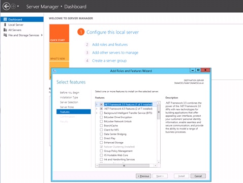
Before you can create a failover cluster you must first ensure that any nodes you wish to join to the cluster have the "Failover Clustering" feature enabled in the Windows Server Roles and Features console. This feature is responsible for providing the failover cluster capability, it uses a set of DLLs and management tools to allow administrators to be able to configure and administer the cluster. The feature can be enabled in one of the following ways;
- Server Manager Dashboard > Add roles and features wizard
- command line using (where ? is the source media drive letter.
DISM /Online /Enable-Feature /FeatureName:FailoverCluster-Mgmt /All /LimitAccess /Source=?:\sources\sxs
Install-WindowsFeature -Name "Failover-Clustering"
Note: The above commands may also be used to enable the .NET 3.5 Framework too, by substituting the featurename with /FeatureName:NetFX3 (DISM) or -Name "NET-Framework-Core"(PowerShell).
Option enabled in Server Roles and Features
Image 4.0
Before creating your cluster you must also ensure that all potential nodes have the same Windows software patch level, also ensure that the nodes use the same driver versions. Having a cluster with one node having a different network card driver for instance, can lead to a whole lot of trouble, not least it will likely fail the cluster validation.
Remember from stairway level 3, we also need a solid DNS infrastructure, an Active Directory domain and a TCP/IP network for the Microsoft Client Network protocol to communicate over. If you need to, make a quick review of level 3 for full details of the above.
Cluster IP and Name Configuration
Once the failover clustering feature is installed and you have satisfied the infrastructure requirements, you will need to decide on the Virtual IP address and the Virtual Networkname you will be using (Generally these will be assigned by a system administrator), these are both required for the Cluster Client Access Point. This is the name or IP address you will use to connect to the Windows cluster when managing cluster objects. Using our intended 5 node cluster, I am using the following assignments
Node and Virtual Networkname IP assignments
| Computername |
IP Address |
| ClusterNode1 |
192.168.0.171 |
| ClusterNode2 |
192.168.0.172 |
| ClusterNode3 |
192.168.0.173 |
| ClusterNode4 |
192.168.0.174 |
| ClusterNode5 |
192.168.0.175 |
| WIN2K12R2-01 |
192.168.0.176 |
You will notice in the list above, an extra computer name and IP address, this is the Client Access Point for the Windows Server Failover Cluster. Learning from Level 3, each clustered instance of SQL Server or AlwaysOn listener that is installed, will also use a Virtual Computer Object and Virtual IP address. By the end of the final level of this stairway we will see at least 2 more Virtual Computer Objects and Virtual IP addresses.
When connecting to the cluster you would use WIN2K12R2-01 or 192.168.0.176, this is the Cluster Client Access Point detailed above.
Note: Failover Cluster Manager also allows you to connect to a cluster by specifying details for one of the cluster nodes or one of the cluster roles within the Windows cluster.
Windows Cluster Network Configuration
When you create a cluster in Windows Server 2008\2012, the cluster-networking driver detects and creates the networks based on whether or not a default gateway is bound to a network adapter. If a default gateway is detected, that network is set to allow clients to connect and it's also marked for use by cluster communications. Storage networks such as iSCSI, will be unavailable for all cluster communication.
Ensure that all networkadapters on each node are named appropriately for the intended network use (e.g. Public, Private, iSCSI, etc), this makes cluster network management much easier via the Failover Cluster Manager application. You must also ensure you set any network adapter connection priorities. With Public, Private and iSCSI interfaces the priority list from preferred to least would be
- Public
- Private
- iSCSI
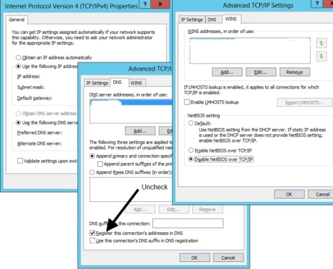
On all non client networks, in this case Private and iSCSI, you must also uncheck the "Register this connection in DNS" checkbox and disable NetBIOS over TCP/IP. These options are found in the network adapters advanced TCP IP settings, you may open the advanced settings as follows;
- Find the network icon in the system tray and right click, select “Open Network and Sharing Center”.
- In the Network and Sharing Center select the option to “Change adapter settings”.
- Right click your chosen adapter and select “Properties”.
- Locate the “Internet Protocol Version 4 (TCP/IPv4)” protocol and select “Properties”.
- Click the “Advanced” tab and select the “DNS” or “WINS” tabs
A screenshot is shown below in Image 4.1
Image 4.1
Windows Server Cluster Service
The Cluster service controls server cluster operations and manages the clusters internal flat file database. A cluster is a collection of independent computers that act as a single entity. Managers, programmers, and users see the cluster as a single system. If a node failure occurs, other nodes provide the services and data that were formerly provided by the missing node. When a new node is added to the cluster, any clustered applications such as SQL Server Failover Cluster Instances must be re installed to that node.
The following provides details of the network requirements for the Windows Cluster service
Windows System service name: ClusSvc
Ports required
| Application |
Protocol |
Ports |
Description |
| Cluster Service |
UDP |
3343 |
|
| Cluster Service |
TCP |
3343 |
Required during a node join operation |
| RPC |
TCP |
135 |
|
| Cluster Administrator |
UDP |
137 |
|
| Randomly Allocated High UDP Ports |
UDP |
|
Random port number between 1024 and 65535 |
| |
|
|
Random port number between 49152 and 65535 (Windows 2008 on) |
For more detail see the link below
http://support.microsoft.com/kb/832017
Creating the Windows Server Failover Cluster
Let's now have a look at the process to create the Windows Server Failover Cluster. The default tool available is the"Failover Cluster Manager" console, this is shown below in image 4.2. You may also use Powershell to manage your cluster, consult the "FailoverClusters" module documentation for more details of the Cmdlets available.
If you haven't already, on each node, from the "Server Manager" dashboard, add the "Failover Clustering" feature using one of the methods detailed above. Once all 5 nodes have the feature installed, give each node a reboot to ensure all pending actions are cleared.
On Node1, from the "Server Manager" > "Tools" option, open the "Failover Cluster Manager" application. Click the "Create Cluster" option, if no validation has been previously performed the cluster validation will start first.
Image 4.2
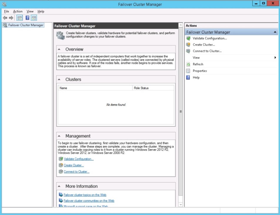
Image 4.3
Click "Next" to continue. See Image 4.4
Image 4.4
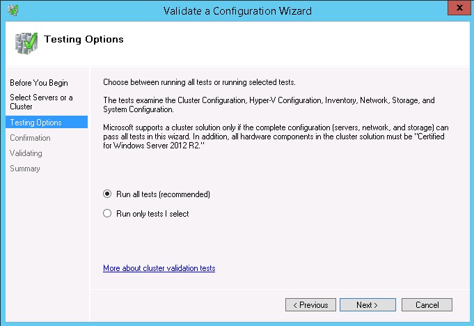
Select the test options and click "Next". See Image 4.5
Image 4.5
Click "Next" after reviewing a summary of the configuration you have selected. See Image 4.6
Image 4.6
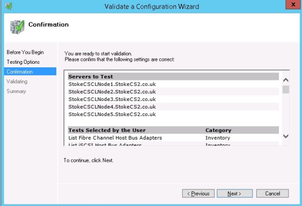
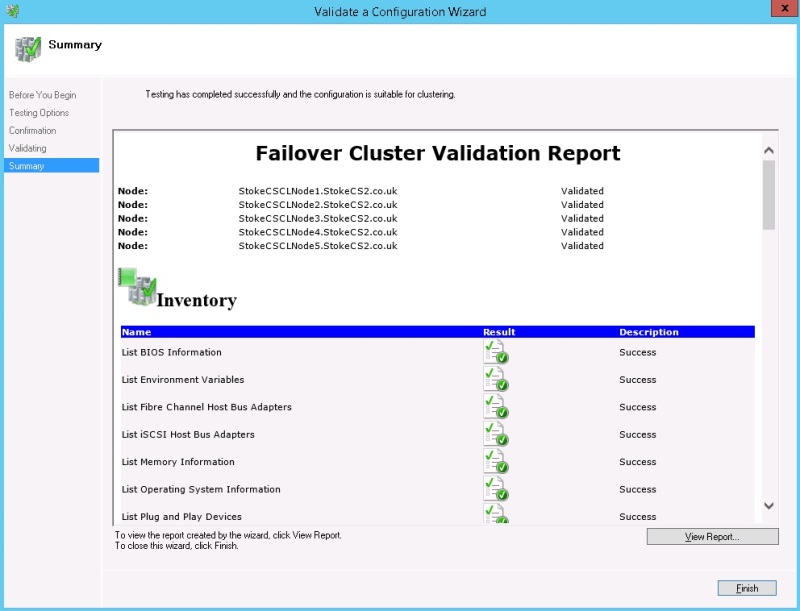
Image 4.7
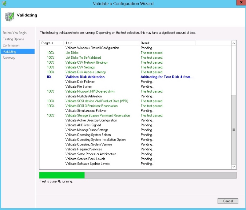
Once the validation finishes, review your cluster validation report and ensure success. With the "Create the cluster now using the validated nodes" checkbox selected, click "Finish", this will invoke the "Create Cluster" wizard. See Image 4.8
Note: If you have any failures you must remedy these first and re run the validation until successful.
Image 4.8
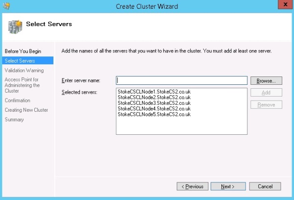
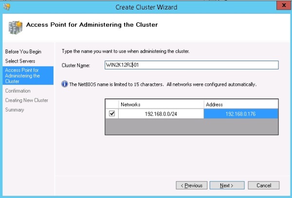
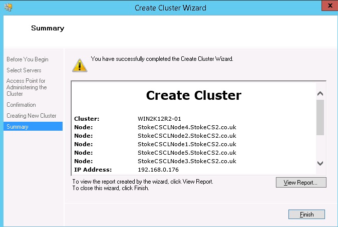
When the "Create Cluster" wizard starts you will be required to supply a unique virtual networkname and a unique virtual IP address for the Cluster Client Access Point. As detailed at the start of this level I will be using the following values
Virtual Networkname WIN2K12R2-01
Virtual IP Address 192.168.0.176
Let's take a short paragraph here to discuss the VNN and VIP a little more.
When referred to as Virtual, this merely means assigned to the client access point, which in itself is a virtual connection point. For the virtual IP address and network name, the following apply
· The virtual IP address should be unique within the network range
· The virtual networkname follows the same rules as an ordinary computername which would be assigned to a Windows computer
· The virtual networkname should be a unique computername within the Windows domain
Just select a valid, but unique IP address and computername, these are usually assigned by your network and\or domain administrators. The values you supply will be validated at this point, if successful click "Next" to continue. See Image 4.9
Image 4.9
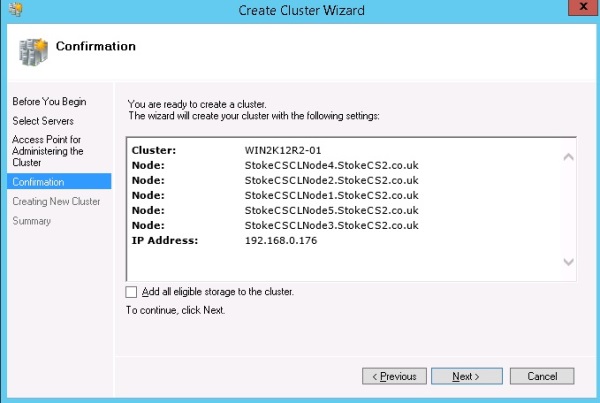
At this point I prefer to remove the option to automatically add eligible storage, If I'm deploying a cluster which will use shared storage to service a Failover Cluster Instance, I like to have manual control of what is and is not added, we'll see more in the next steps. To disable the addition of storage, deselect the "Add all eligible storage to the cluster" checkbox and click "Next". See Image 4.10
Image 4.10
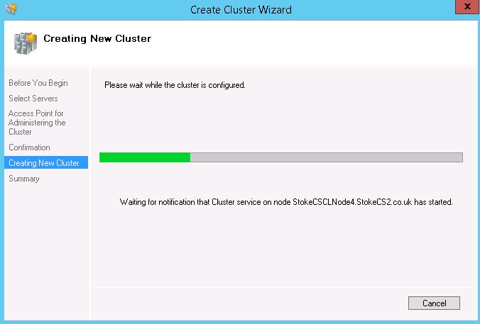
Below is an example of the cluster configuration in process. See Image 4.11
Image 4.11
Click "Finish" to create the cluster. See Image 4.12
Image 4.12
Now, since our cluster will be used to cover a deployment of a Failover Cluster Instance we should provision and then add to the cluster our shared storage devices. This is not detailed here, if you're using iSCSI you may refer to my article at the following links which shows how to create and present LUNs from a virtual storage server.
SQL Server 2012 FCIs Part 1
http://www.sqlservercentral.com/articles/AlwaysOn/98619/
SQL Server 2012 FCIs Part 2
http://www.sqlservercentral.com/articles/AlwaysOn/106314/
When shared disks are presented to a Windows 2008\2012 server, the default policy is to offline the device(s) on all nodes. For my Failover Cluster Instance I have presented 5 LUNs, these need to be brought online in order to be added to the cluster as disk resources.
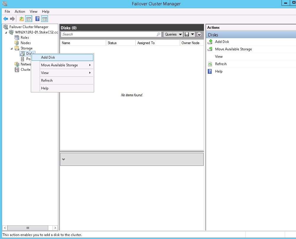
On Node1 open Computer Management and bring online the root drive and 4 mounted volumes.In the "Failover Cluster Manager", right click Disk storage (shown below) and select "Add Disk". See Image 4.13
Image 4.13
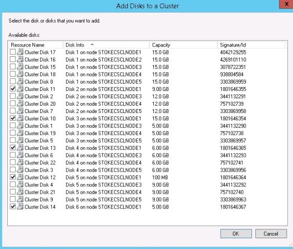
I have all the volumes required online on Node1, so these are the disks I select as shown below. See Image 4.14
Image 4.14
Configuration Note:
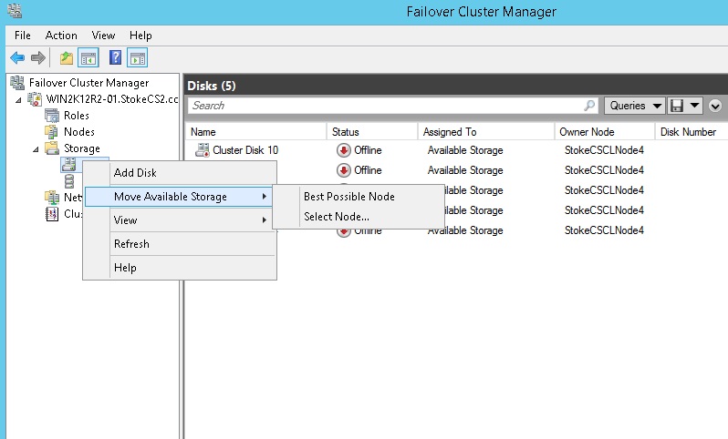
If when the disks have been added they complain that the storage is not connected to the current node, the cluster manager has attempted to online the disks on a node where the storage has not been presented, helpful huh? To remedy this, right click "Disks" and select "Move available Storage" and using the "Select Node" option, move the resources to Node1. See image 4.15
Image 4.15
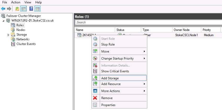
In the "Failover Cluster Manager" main dialog, right click "Roles" and select "Create empty role". Give the role a meaningful name as shown below. Ensure the role is owned by Node1, if it isn't simply move it. With the group owned by the correct node, right click the role and select "Add Storage". See Image 4.16
Image 4.16
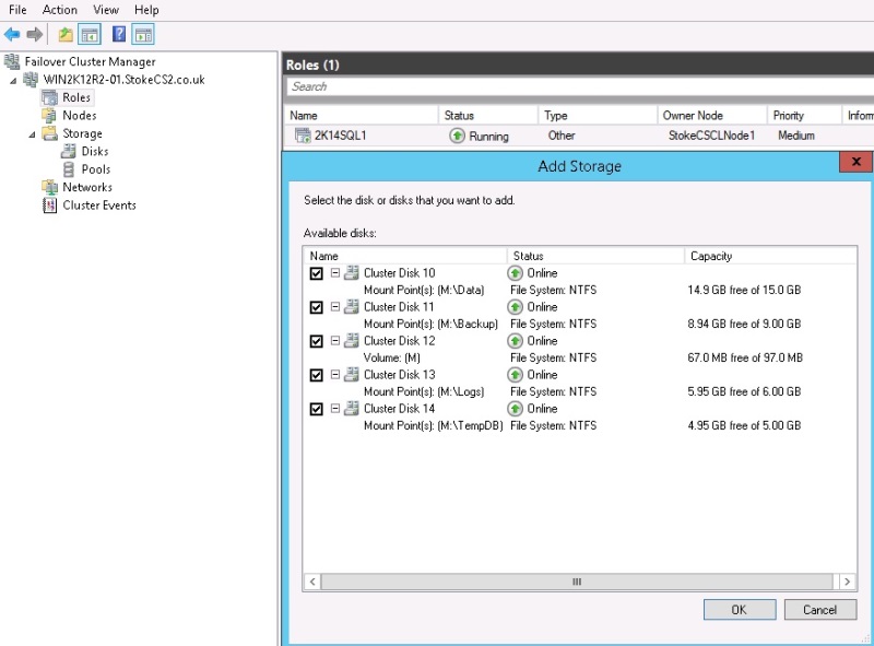
These are the disks I'll be adding to the new role, click "OK" here. See Image 4.17
Image 4.17
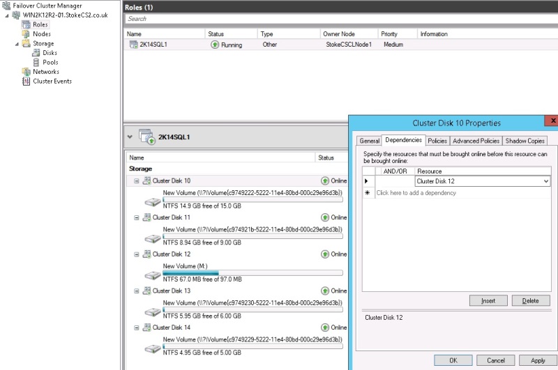
When using mounted volumes, as I am here, it is a best practice to set the disk dependencies, the root drive must always be online before the mounted volumes. To set the disk dependencies for each of the mounted volume disks (10, 11 13 and 14 in my case), open the resource "Properties" and on the "Dependencies" tab add the root drive cluster disk to the resource list. Click "OK" to complete, do this for each mounted volume. See Image 4.18
Image 4.18
The shared disks have now been added to the cluster. Before going any further, don't be afraid to experiment a little. Perform the following and observe the results
· Take the root drive offline, all mounted volumes should go offline first
· Right click the role you created and select "Start Role", all volumes come online
· Move the role back and forth between Node1 and Node2
· Take the root drive offline. Once all volumes go offline, select one of the mounted volumes and bring it online
· Right click the role and select "Stop Role"
· Right click the role and select "Start Role"
You should now have an excellent grasp of the cluster creation process as well as a firm understanding of how to add cluster disk resources.
Although we mention and configure shared disk resources, what would you do if you wanted to use stand alone instances of SQL server with no shared storage?
Simple, don't present any shared storage to the nodes and you'll have no shared disks to configure
Quorum within the Windows Cluster
Now it's time to look at the Quorum.
This subject has been a somewhat major cause of confusion on the forums in the past, this section will seek to address this topic and remove any area of uncertainty. The Windows cluster requires some form of mediation to determine resource ownership during the normal cluster operation. Mediation is necessary to avoid the situation where a catastrophic failure causes multiple nodes to attempt to claim the same resources. Let's start by reviewing the Quorum modes available to us, they are as follows;
Node majority (no witness)
Only nodes have votes. No quorum witness is configured. The cluster quorum is the majority of voting nodes in the active cluster membership.
Node majority with witness (disk or file share)
Nodes have votes. In addition, a quorum witness has a vote. The cluster quorum is the majority of voting nodes in the active cluster membership plus a witness vote.A quorum witness can be a designated disk witness or a designated file share witness.
No majority (disk witness only)
No nodes have votes. Only a disk witness has a vote. The cluster quorum is determined by the state of the disk witness.
The cluster has quorum if one node is available and communicating with a specific disk in the cluster storage. Generally, this mode is not recommended, and it should not be selected because it creates a single point of failure for the cluster.
Windows 2012 R2 now offers "Dynamic Node Weight" configuration, this feature has been specifically designed to prevent cluster outages during planned shutdown of cluster nodes. Let's now look at the quorum in detail and also the new dynamic option to see how this works. We'll look firstly at Windows 2008 and then Windows 2012.
We'll digress here briefly and evict node 5 from the cluster. Right click node 5 in the "Nodes" container and select "Evict Node", follow the wizard and you'll be left with a 4 node cluster.
Windows 2008
We have 4 nodes each with an active vote, ordinarily under Windows 2008, we would receive cluster warnings stating that the quorum configuration does not meet the recommended practice. We would be required to introduce a witness to increase the number of active votes to 5. In the present configuration, a failure of 2 nodes in the 4 node Windows 2008 cluster would result in the cluster services going offline to avoid the "split brain" scenario. Execute the following PowerShell script on a Windows 2008 cluster and you'll see the configuration information available to you, it's fairly limited.
Get-ClusterNode | ft *
Windows 2012
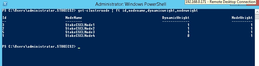
However, within the Windows 2012 cluster, voting has now been dynamically managed for us. Looking at the results below for our quorum configuration, we can see that each node has an equal weight or vote (Node Weight parameter), but look, Dynamic Node Weight has re balanced the cluster for us. Node 1 has had its vote dynamically revoked to keep the vote configuration to an odd number of nodes. See Image 4.19
Note: In Windows 2012 R2, the only way to turn off Dynamic Node Weight is via Powershell, it's recommended that you don't though
Image 4.19
Now let's add in a fileshare witness and we'll re check the difference;
Right click the cluster name in the Failover Cluster Manager console and select "More Actions" > "Configure cluster quorum settings". This will launch the configuration wizard, the first selection available is shown below. Selecting the "Advanced quorum configuration" option and clicking "Next" will proceed to advanced options. This is shown in the next dialog screenshot. See Image 4.20
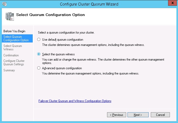
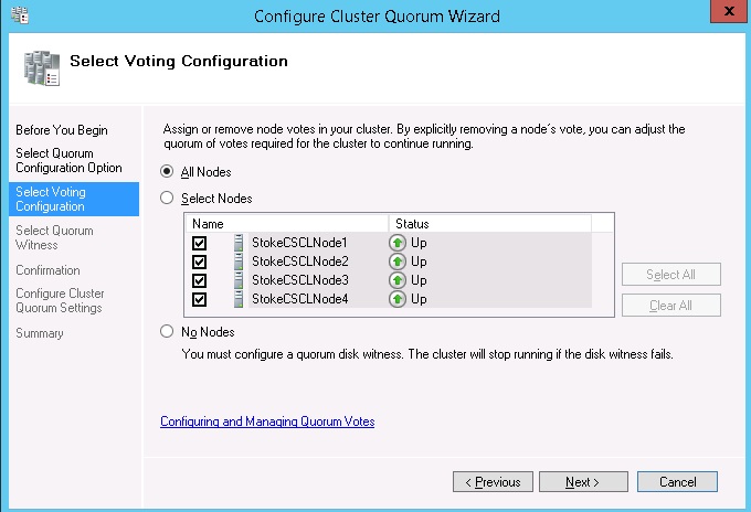
These are the advanced options, note that you can elect certain notes for cluster voting or none or all. Clicking "Next" takes you to the "Select quorum configuration option" screen. See Image 4.21
Image 4.21
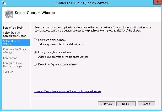
I'm electing to configure a fileshare witness, click "Next" to continue. See Image 4.22
Image 4.22
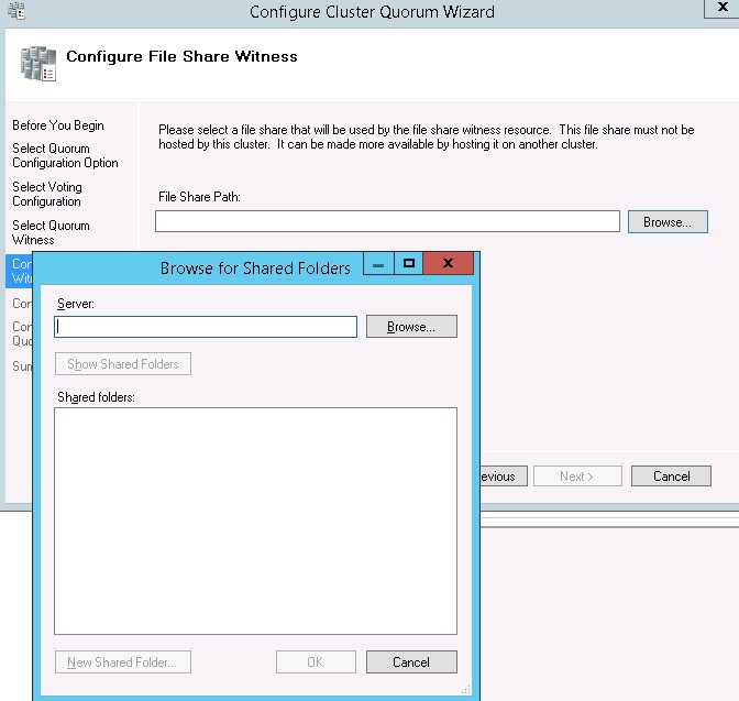
You may browse for and create the share all in one operation. The browser below will allow you to select the server to store the fileshare (the DC\SAN in this case). See Image 4.23
Image 4.23
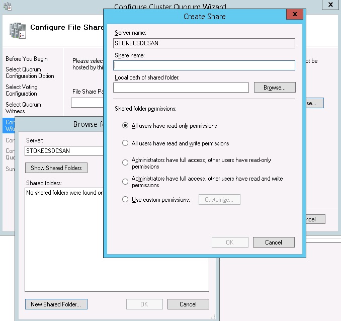
Create the share by supplying a share name, local path on the DC\SAN server and permission level (Admin full, users read will be sufficient). Click "OK" to continue. See Image 4.24
Image 4.24
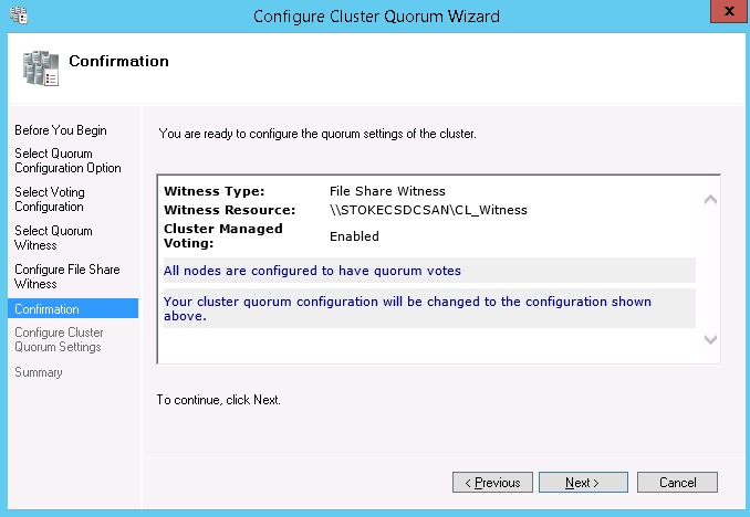
Click "Next" to proceed and complete the configuration. See Image 4.25
Image 4.25
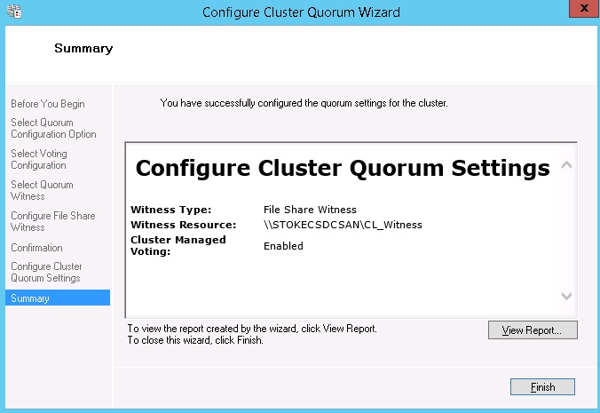
Click "Finish". See Image 4.26
Image 4.26
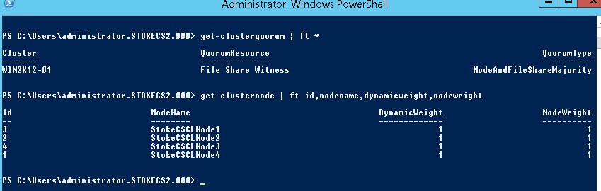
Rechecking the node vote configuration and the quorum mode, we can see the following (See Image 4.27);
· Quorum type is now Majority Node Set and Fileshare Witness.
· All nodes have an active vote in the quorum, Dynamic Node Weight has not intervened as the quorum type now meets the required configuration for our number of cluster nodes.
Image 4.27
To finish the quorum configuration discussion, as a small test exercise, go ahead and shutdown random nodes. Re run the PowerShell query above and check the information returned, what differences do you see?
Once you've completed the tests above, remove the fileshare witness using the wizard selecting "Node Majority" only. Now add node 5 back by right clicking the "Nodes" container and select "Add Node", this is wizard driven and fairly self descriptive, it's also a good way to test your new found clustering skills. As a real challenge, why not see if you can add the node using a Powershell query.
That completes the Windows Server Failover Cluster level, you should now have a firm grounding with the Windows operating system, the failover cluster manager application and the quorum configuration requirements. You should now have a virtual cluster that is both stable and ready to receive a Failover Cluster Instance of SQL Server or Stand alone instances to service an AlwaysOn Availability group configuration.
We'll look at Failover Cluster Instances in detail in Level 5 of the stairway and also step through the deployment process.
As always, work through the article and if you have any questions or get stuck in any way, post back in the discussion thread.
 Subscribe